
Service mesh. Host shared proxy. Sidecar containers. If these terms are unfamiliar, don’t worry. Service mesh a relatively new concept and – judging by the amount of available documentation, public discussion, and GitHub activity – it’s just beginning to be to adopted, following in the footsteps of containers and microservice based architectures. And it is just as beneficial. This article will help you understand the basics of service mesh, the infrastructure benefits of service mesh, and a hands-on tutorial so you can try it.
The two main goals of a service mesh are to allow insight into previously invisible service communications layers and to gain full control of all microservices communication logic, like dynamic service discovery, load balancing, timeouts, fallbacks, retries, circuit breaking, distributed tracing, and security policy enforcement between services. The insights are provided by traffic audit and tracing features.
Kubernetes already has a very basic “service mesh” out-of-the-box; it’s the “service” resource. It provides service discovery by targeting the needed pods, and a round-robin balancing of requests. A “service” works by managing iptables on each host in the cluster, allowing only a round-robin load balancing approach, with no retries and back off logic, and no other features that we might expect a modern service mesh to handle. However, implementing one of the fully featured service mesh systems in your cluster (Linkerd, Istio or Conduit), will provide you with the following possibilities:
- Allow services to talk plain HTTP and not bother about HTTPS on the application layer: The service mesh proxies will manage HTTPS encapsulation on the sender side and TLS termination on the receiver side, allowing the application components to use plain HTTP or gRPC and any other protocol without bothering with encryption in transit. The encryption is taken care of by the proxies.
- Security policies enforcement: the proxy knows which services are allowed to access some other services and endpoints and will deny unauthorized traffic.
- Circuit breaking: automatic back off in case of accessing an overloaded service or endpoint, that has a high latency already, to avoid hitting it with more and more requests which may cause that endpoint to fail completely under an excessive load.
- Latency aware load balancing: instead of using a round-robin style of balancing (which ignores the latency of each target), use smarter balancing according to response times of each backend target. This is an incredibly important feature of a modern service mesh.
- Queue depth load balancing: route new requests based on the least busy target by current request processing amount. The service mesh knows exactly where it has sent all previous requests, and which of them are still processing or completed, so it will send new incoming requests based on that logic to a target with the lowest queue for processing.
- Per request routing: route particular requests marked by selected HTTP header to specific targets behind the load balancer, allowing easy canary deployment testing and other creative use cases. One of the most powerful features a service mesh provides.
- Health checks, retry budgets, and eviction of misbehaving targets.
- Metrics and tracing: reporting of requests volume per target, latency metrics, success and error rates.
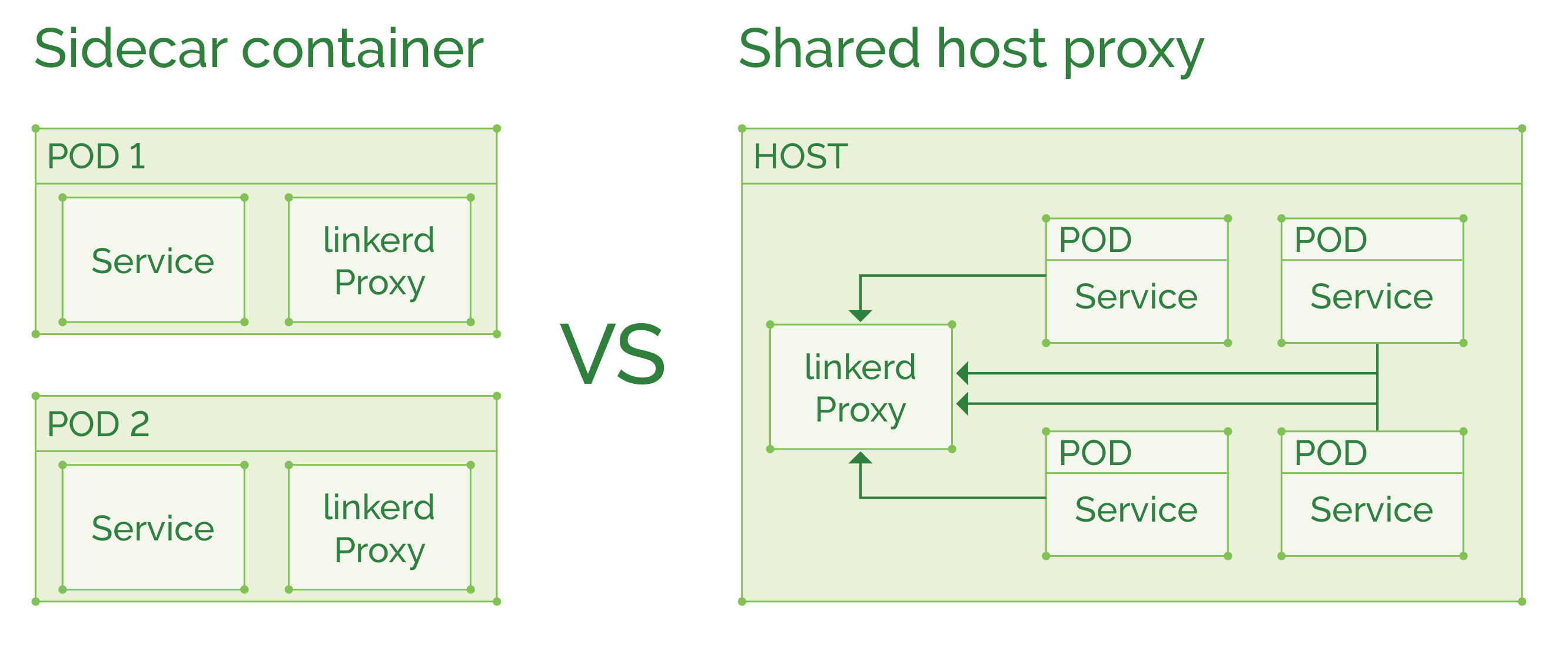
There are two main patterns for deploying a service mesh:
As a host shared proxy, a DaemonSet in Kubernetes terms. This type of deployment will use fewer resources if many containers exist on the same host and might also utilize connection pooling to improve throughput. But a failure in one proxy terminates the whole fleet of containers on that host, instead of breaking a single service (if it was used as a sidecar proxy).
As a sidecar container, where the proxy is injected into each pod definition to run alongside the main service. In case of more “heavyweight” proxy like Linkerd, this deployment will cost you additional ~200MB of memory per pod. But if using the newer Conduit, will only cost ~10MB per pod. Conduit does not have yet all the features Linkerd has, so we’ve yet to see a final comparison of the two. Usually a “sidecar container per pod” is a good choice, limiting possible proxy failure to a single pod, and will not affect other pods on the same host.
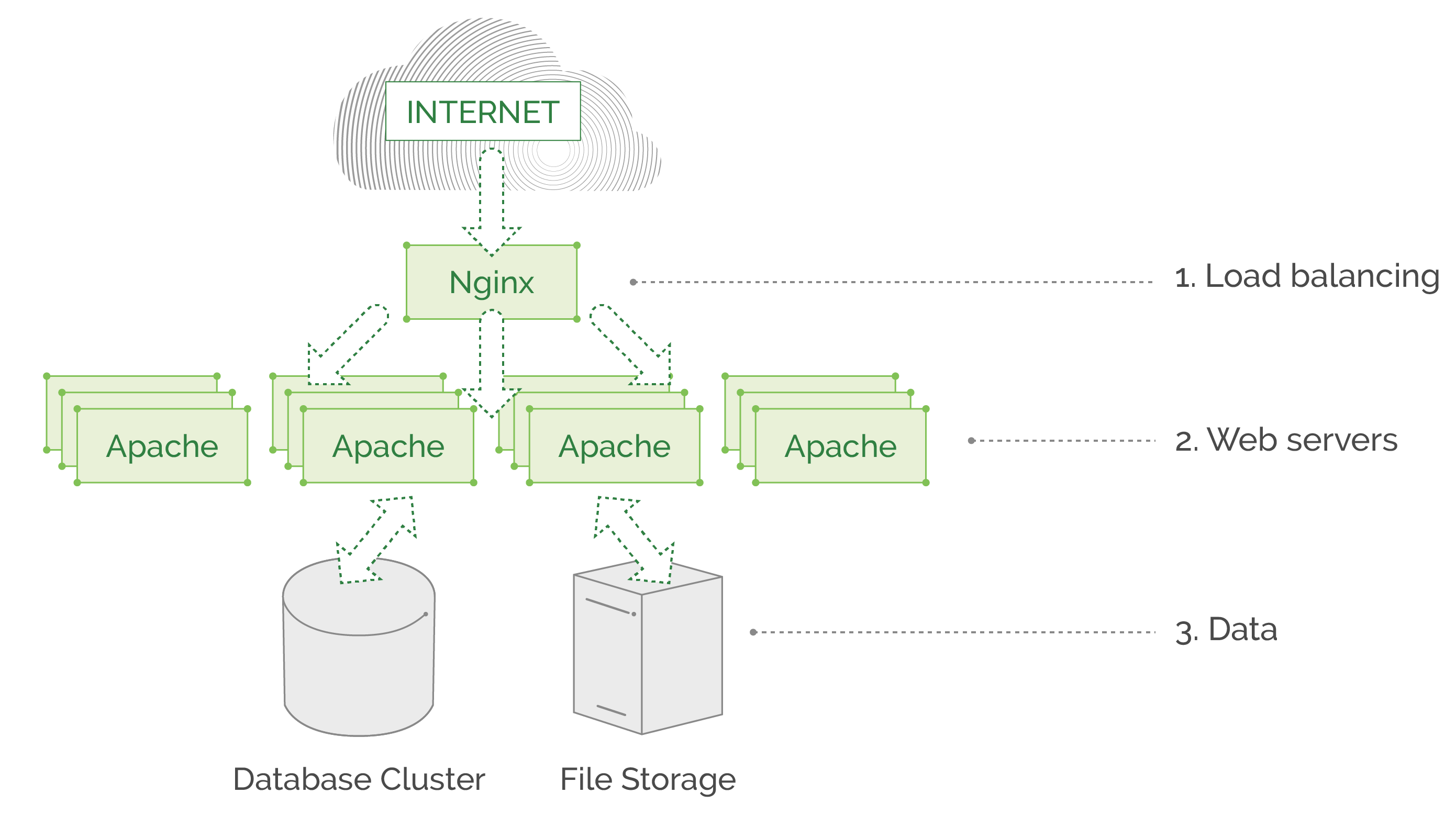
Why do you need to create a service mesh pattern? Let’s look at two diagrams of different types of application architectures to illustrate the need.
The first example is an old-fashioned, three-layer web service that is written as a monolith all-in-one application. It may serve millions of requests daily, but has no complex features, and the communication of the underlying service is straightforward and simple: Nginx balances all traffic to Apache instances, which in turn fetch data from database\file storage and return the needed page. This example architecture will not benefit that much from a service mesh, as this monolith has no code written by developers that takes care of routing and communicating between application components because there are no microservices involved. In a monolith application, all core components are located on the same machine and do not communicate over the network, there are no REST APIs or gRPC. All “business logic” is within a single application, deployed as a whole piece on each Apache web server.
The second example is a modern microservice based application with a lot of processes and behind the scenes logic. It does so many things, like learning visitor patterns and preferences to personalize their experience on the website, notifying users about their favorite topic updates, and so on. You can imagine the many complicated processes that happen between all these microservices, spread across thousands of containers and hundreds of nodes. Please note that our illustration is extremely simplified. In reality, we would lose count of the objects on screen if we were to display a real architecture of a large cloud-native application.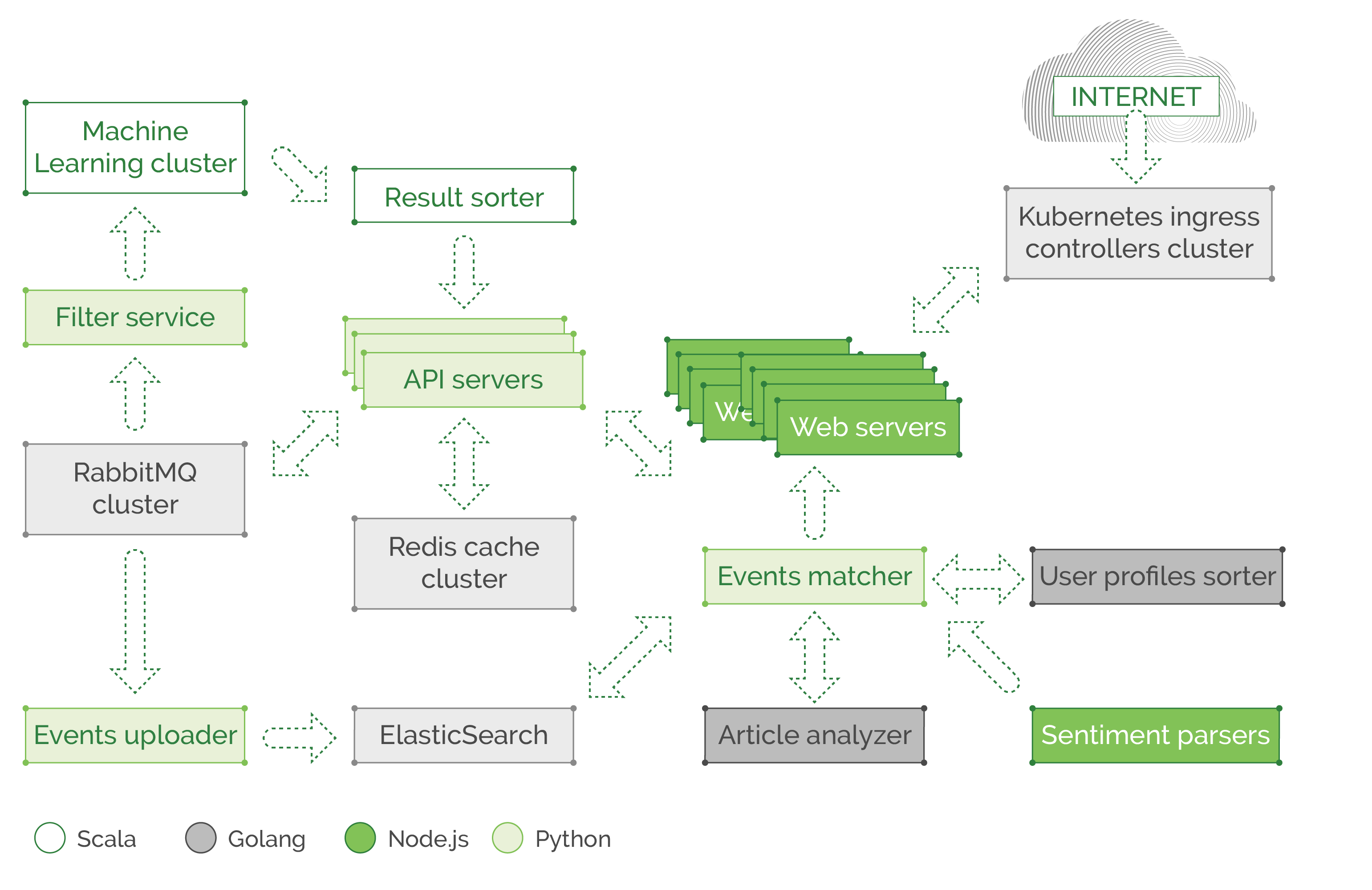
In this example, we would have a piece of code in each microservice, that is related to communication. It sets the retry policies, timeouts, exception handling (in case of network failures), and the like. We also see a polyglot environment where teams created their component in Scala, some use Golang, Node.js or Python. All components can talk to each other through REST API or gRPC over the network, and each team spends time and effort implementing communication logic in their own component, using their respective language of choice, so they can’t share each other libraries and functions, to at least save time and use a unified solution plugged into all components of the application as a dependency. In addition to functions that query the service discovery mechanism (like Consul or ZooKeeper) or read some config passed externally to the application, there is a need to report latency and response-related metrics to Prometheus/InfluxDB. This includes information about cache response time (redis or memcached cache) which is usually located on another node or as a whole separate cluster, that might be overloaded and causing high latency. And all that is part of the service code and needs to be maintained in addition to the teams exploding backlog, and deadlines approaching. Developers hate to spend time on ops related parts of their code, like adding tracing and metrics (for ops to enjoy when troubleshooting and analyzing) or dealing with possible network failures, implementing fallbacks, and retry budgets.
In this kind of environment, a service mesh will save development time, and allow a unified way to control the communication in a central fashion. So how do we change this communication layer mechanics to a unified “service mesh?” We take all of that microservice communication, routing, discovery, latency metrics, request tracing, and similar parts of microservice code, and move it outside the service completely, to form a standalone proxy process that knows how to handle all that (and much more) for each of the microservices. Luckily these tools already exist! Companies like Twitter, Lyft, and Netflix have open sourced their solutions, and other contributors also built their own tools on top of the open-sourced libraries. At the moment there are several major options to use as service mesh: Linkerd, Conduit, Istio, and Envoy. Istio is a component built on top of Envoy, it’s a control plane that can be used with both Envoy and Linkerd as its data plane proxies. The control plane allows a cluster operator to set particular settings in a centralized fashion, which will then be distributed across the data plane proxies and reconfigure them.
Both Linkerd and Conduit are built by Buoyant, a team of ex-Twitter engineers. At the moment Linkerd is the most-used service mesh, but Conduit was built from scratch specifically for Kubernetes to be a lightweight proxy sidecar, that is extremely fast and ideal for Kubernetes environments. At the moment of writing, Conduit is still under active development.
Let’s look at the change from application dependent communication logic, to “service mesh” pattern.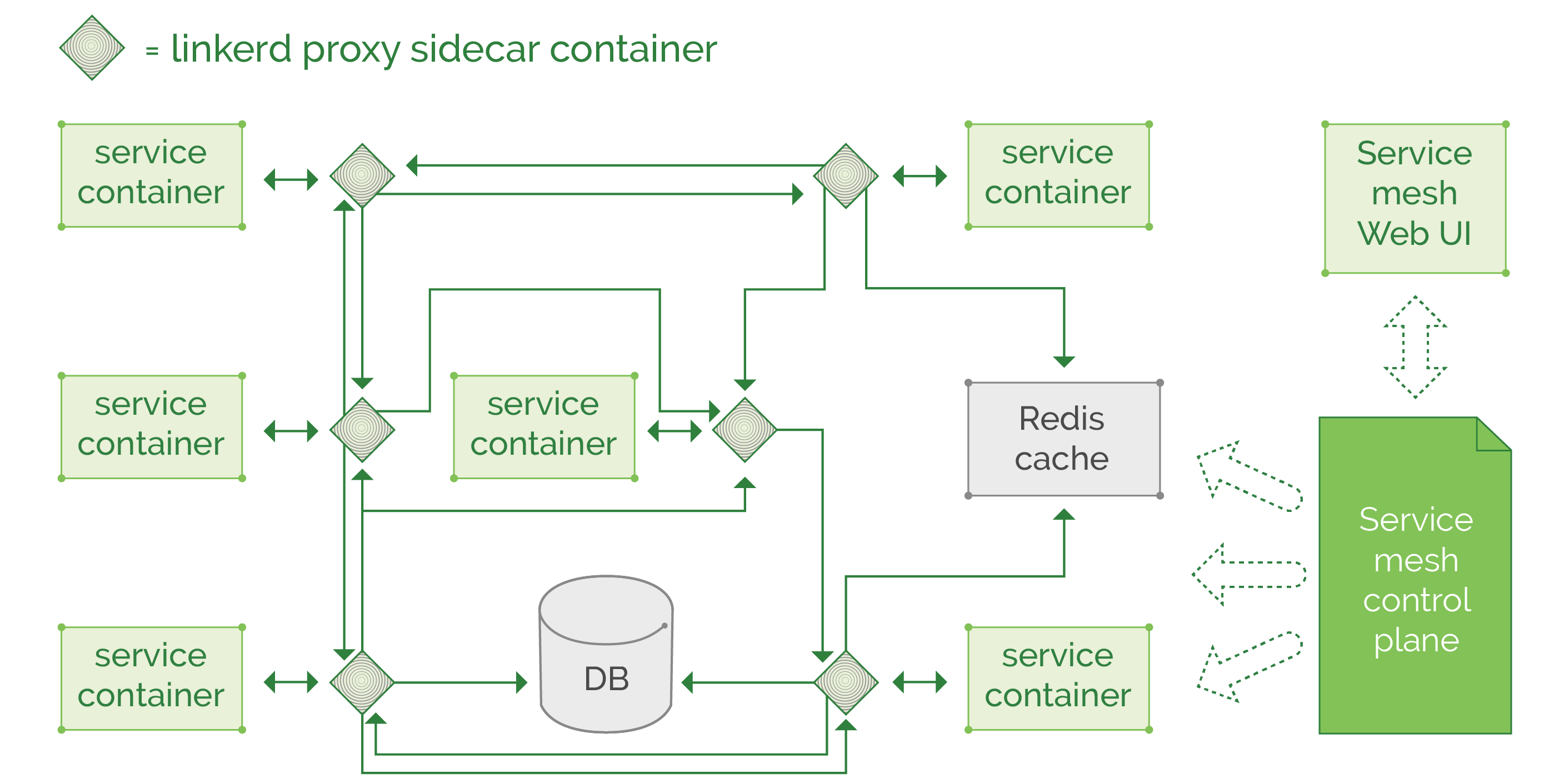
The best thing to note is all those proxies can be configured and updated in the same place, through their control plane (or through configuration files in some repository, depends on the chosen tool and deployment method), and we can apply a particular set of rules on all thousands of proxies. So, the routing, balancing, metric collection, security policy enforcement, circuit breaking, data in transit encryption, all those actions will follow a strict set of rules, applied by the cluster administrators.

Is Service Mesh Right for You?
At first glance, this new concept of decoupling the microservice communication mechanics into separate architecture layer raises a question: Is it beneficial enough to be worth the complexity of configuring and maintaining a whole fleet of special proxies?
To answer that question, you’ll need to estimate the size and complexity of your application. If you have just a few microservices and data storage endpoints (for example one ElasticSearch cluster for logging, one Prometheus cluster for the metrics, with two or three databases for main application data) implementing a service mesh might be an overkill for your environment. However, if you have your application components spread through hundreds or thousands of nodes, with 20+ microservices, your environment will benefit greatly from the features a service mesh provides.
Even in a smaller environment if you prefer to decouple the retries and circuit breaking behavior from the application itself (from the code that manages reconnection and back off, for example, to avoid overloading other services or databases with retries) you can use the service mesh to remove this networking logic maintenance burden from your application developers, so they will focus more on the business logic instead of being involved in managing and tweaking intercommunication of all microservices. The ops team will configure the service mesh once, and tweak from time to time in a centralized fashion, minimizing the effort spent on application components communication.
Istio is a perfect example of a full feature service mesh, it has several “master components” that manage all “data plane” proxies (those proxies can be Envoy or Linkerd but by default, it is Envoy so that’s what we’ll use in our tutorial while Linkerd integration is still a work in progress).
Here is a quick diagram of Istio architecture from the official website:
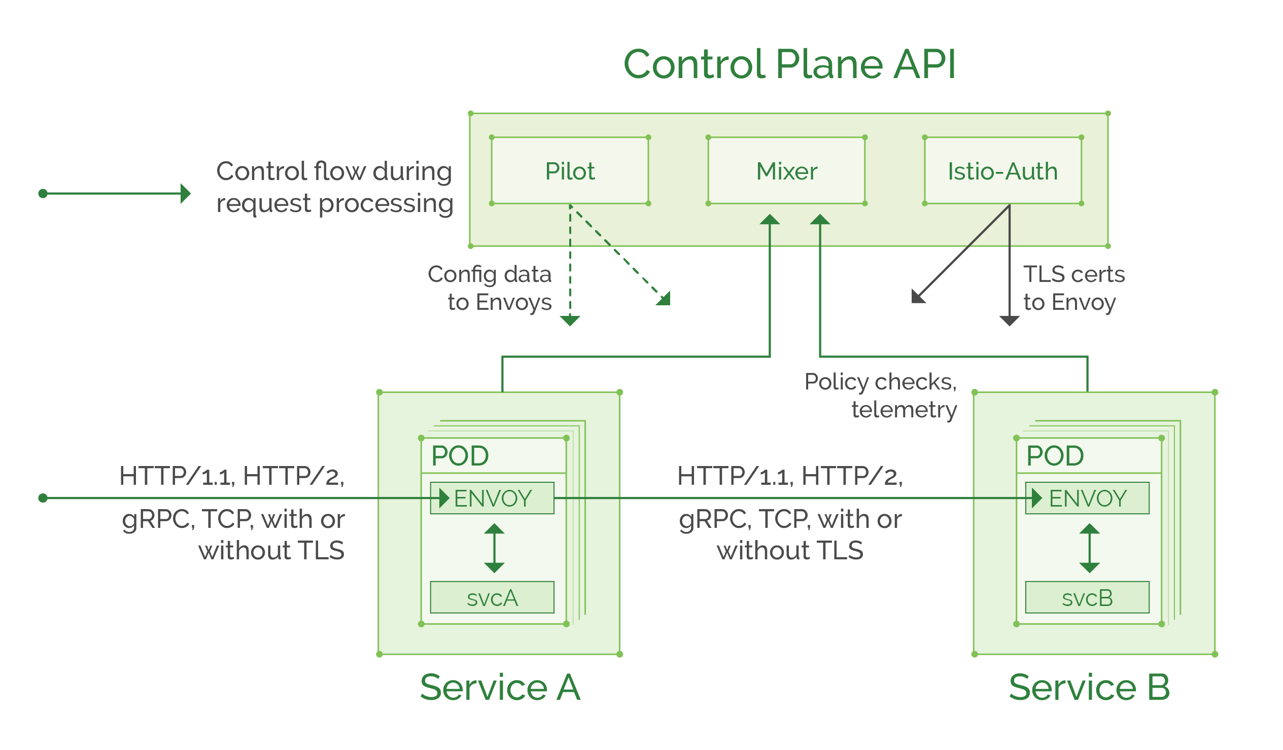
You can read more in the official documentation, but for the purpose of our tutorial, here is a summary of Istio components and their functions:
Control plane:
- Pilot: provides routing rules and service discovery information to the Envoy proxies.
- Mixer: collects telemetry from each Envoy proxy and enforces access control policies.
- Istio-Auth: provides “service to service” and “user to service” authentication and can convert unencrypted traffic to TLS based between services. Soon will be able to provide access audit information (work in progress).
Data plane:
- Envoy: feature rich proxy, that is being managed by control plane components. Intercepts traffic to and from the service and applies the needed routing and access policies following the rules set in the control plane.
Tutorial
Tutorial stage 0: Install a Kubernetes cluster
In the following tutorial, we will use the Istio service mesh to demonstrate one of the most powerful features: “Per request routing.” As noted earlier, it allows the routing of particular requests marked by selected HTTP header to specific targets that is possible only with a layer 7 proxy. No layer 4 load balancer or proxy can achieve that functionality.
For this tutorial, we assume you have a Kubernetes cluster running (Hint: you can spin up a new cluster in a matter of minutes, following these instructions, or use “Kublr-in-a-box” to set up a local cluster in few easy steps). A small cluster with 1 master node and 2 worker nodes should be enough for this tutorial.
Tutorial stage 1: Install the Istio control plane
One option is to follow the official tutorial here, to install the control plane in your Kubernetes cluster. The installation steps depend on your local machine type (Mac, Linux, Windows), so we will not replicate here the standard instructions of setting up local istioctl application and kubectl, the two CLI tools that will be used to manage Kubernetes and Istio. For the impatient but savvy, less detailed instructions are as following (if it doesn’t work use the official instructions step by step):
-
Setup the Kubernetes cluster (using any method listed above, or use your existing testing\development cluster)
-
Install kubectl locally (with it you will manage the Kubernetes cluster).
-
Install istioctl from GitHub release page (that is used to inject Envoy proxy to pods and to set routing rules and policies), the installation is simple:
- For Mac or Linux run
curl -L https://git.io/getLatestIstio | sh -- On windows just extract the zip, and copy binary to your PATH (can simply copy into
c:\windows\system32\) or run allistioctl.execommands from /bin/ directory. - Navigate to the folder with extracted files, and install with
kubectl apply -f install/kubernetes/istio-demo.yaml
You’ll need a Kubernetes client config file and access to the cluster dashboard. How you get them may vary depending on the method used to create the cluster. Since this cluster was deployed with Kublr, you’ll find the following links in Kublr dashboard and download config file to your ~/.kube/config (%USERPROFILE%/.kube/config in windows), then navigate to the Kubernetes dashboard:
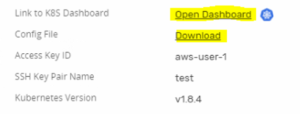
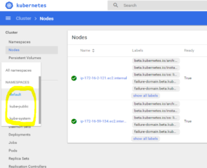
Use the credentials from the config file (locate the “username: admin” and use this user and its listed password to login to dashboard). You should see the dashboard, and clicking the default “namespace” in the sidebar will reveal the following 3 default namespaces:
Istio components will be installed into their own namespace. Navigate to the folder where you downloaded Istio release archive, extract, and run:
kubectl apply -f install/kubernetes/istio-demo.yaml
You will see a lot of components being created, each of which is described in the official documentation, or you can open the yaml file to have a look at the comments, every resource is documented in that file. Then we can browse the namespaces and check if everything was created successfully:
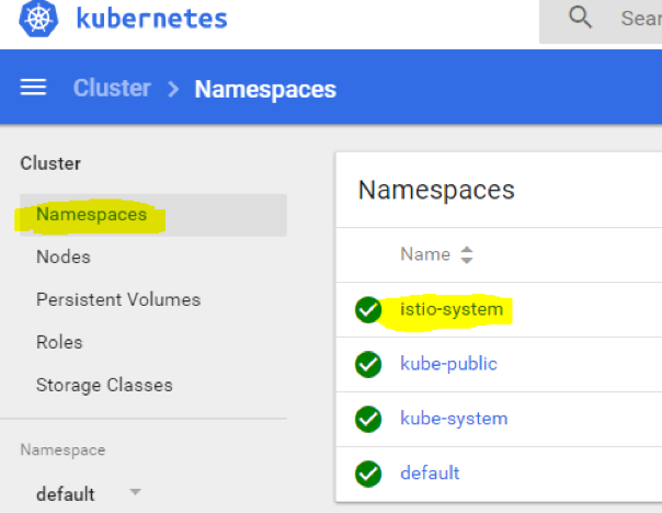
Click istio-system and make sure there were no errors or issues during components creation. It should look similar to this:
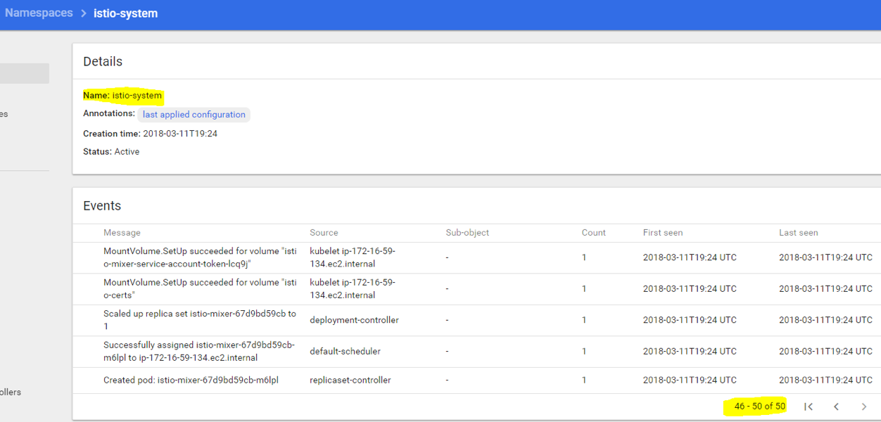
There are about 50 events, you can scroll to see “successful” statuses, and will notice if there’s an error somewhere. In case of errors, you can post a bug report on Istio GitHub issues page, to point the developers to the issue.
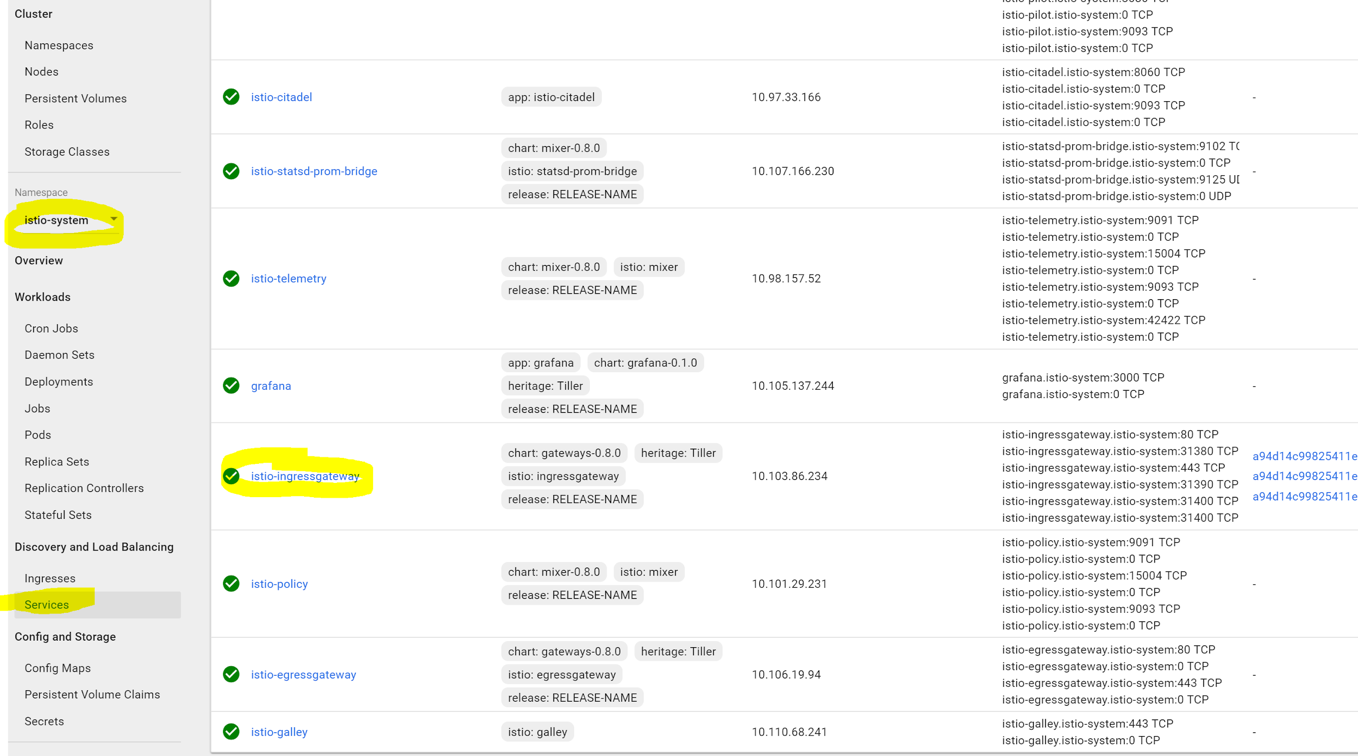
We need to find the entry point of the istio-ingress service, to know where to send traffic to. Navigate to “istio-system” namespace in the sidebar. If it’s not visible among other namespaces right after creation, simply refresh the browser page, then select that namespace, click “services” and find the external endpoint as shown on the following screenshot:
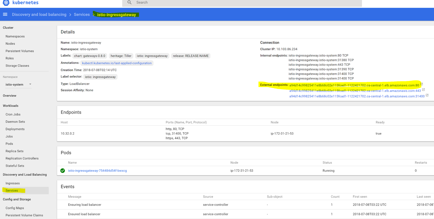
In our case, it is an AWS elastic load balancer, but you might see an IP address, depending on the cluster setup. We will access our demo web service using this endpoint address.
Tutorial Stage 2 – Deploy a Demo Web Service with Envoy Proxy Sidecar
Now we finally are at the fun part of the tutorial. Let’s check the routing capabilities of this service mesh. First, we will deploy two demo web services, “blue” and “green,” like in one of our previous tutorials. Copy the following into a yaml file named my-websites.yaml:
apiVersion: apps/v1beta1
kind: Deployment
metadata:
  name: web-v1
  namespace: default
spec:
  replicas: 1
  template:
    metadata:
      labels:
        app: website
        version: website-version-1
    spec:
      containers:
      - name: website-version-1
        image: kublr/kublr-tutorial-images:v1
        resources:
          requests:
            cpu: 0.1
            memory: 200
---
apiVersion: apps/v1beta1
kind: Deployment
metadata:
  name: web-v2
  namespace: default
spec:
  replicas: 1
  template:
    metadata:
      labels:
        app: website
        version: website-version-2
    spec:
      containers:
      - name: website-version-2
        image: kublr/kublr-tutorial-images:v2
        resources:
          requests:
            cpu: 0.1
            memory: 200
---
apiVersion: apps/v1beta1
kind: Deployment
metadata:
  name: web-v3
  namespace: default
spec:
  replicas: 1
  template:
    metadata:
      labels:
        app: website
        version: website-version-3
    spec:
      containers:
      - name: website-version-3
        image: kublr/kublr-tutorial-images:v3
        resources:
          requests:
            cpu: 0.1
            memory: 200
---
apiVersion: v1
kind: Service
metadata:
  name: website
spec:
  ports:
  - port: 80
    targetPort: 80
    protocol: TCP
    name: http
  selector:
    app: website
Note that when you want to use the Envoy sidecar with your pods, the label “app” should be present (it’s used in the request tracing feature), and “spec.ports.name” in service definition must be named properly (http, http2, grpc, redis, mongo) otherwise Envoy will act on that service traffic as if it was plain TCP, and you will not be able to use the layer 7 features with those services! Also, the pods must be targeted only by 1 “service” in the cluster. As you can see above, the definition file has three simple deployments each using a different version of the web service (v1/v2/v3), and three simple services, each pointing at the corresponding deployment.
Now we will add the needed Envoy proxy configuration to the pod definitions in this file, using “istioctl kube-inject” command. It will produce a new yaml file with additional components of the Envoy sidecar ready to be deployed by kubectl, run:
istioctl kube-inject -f my-websites.yaml -o my-websites-with-proxy.yaml
The output file will contain extra configuration, you can inspect the “my-websites-with-proxy.yaml” file. This command took the pre-defined ConfigMap “istio-sidecar-injector” (that was installed earlier when we did istio installation), and added the needed sidecar configurations and arguments to our deployment definitions. When we deploy the new file “my-websites-with-proxy.yaml”, each pod will have two containers, one of our demo application and one Envoy proxy. Run the creation command on that new file:
kubectl apply -f my-websites-with-proxy.yaml
You will see this output if it worked as expected:
deployment "web-v1" created
deployment "web-v2" created
deployment "web-v3" created
service "website" created
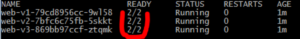
Let’s inspect the pods to see that the Envoy sidecar is present: kubectl get pods
Let’s inspect the pods to see that the Envoy sidecar is present: kubectl get pods.
We can see that each pod has two containers, one is the website container and another is the proxy sidecar:
Also, we can inspect the logs of the Envoy proxy by running:
kubectl logs <your pod name> istio-proxy
You will see a lot of output, with last lines similar to this:
add/update cluster outbound|80|version-1|website.default.svc.cluster.local starting warming
add/update cluster outbound|80|version-2|website.default.svc.cluster.local starting warming
add/update cluster outbound|80|version-3|website.default.svc.cluster.local starting warming
warming cluster outbound|80|version-3|website.default.svc.cluster.local complete
warming cluster outbound|80|version-2|website.default.svc.cluster.local complete
warming cluster outbound|80|version-1|website.default.svc.cluster.local complete
This means that the proxy sidecar is healthy and running in that pod.
Now we need to deploy the minimal Istio configuration resources, needed to route the traffic to our service and pods, save the following manifests into a file named “website-routing.yaml”:
---
apiVersion: networking.istio.io/v1alpha3
kind: Gateway
metadata:
  name: website-gateway
spec:
  selector:
    # Which pods we want to expose as Istio router
    # This label points to the default one installed from file istio-demo.yaml
    istio: ingressgateway
  servers:
  - port:
      number: 80
      name: http
      protocol: HTTP
    # Here we specify which Kubernetes service names
    # we want to serve through this Gateway
    hosts:
    - "*"
---
apiVersion: networking.istio.io/v1alpha3
kind: VirtualService
metadata:
  name: website-virtual-service
spec:
  hosts:
  - "*"
  gateways:
  - website-gateway
  http:
  - route:
    - destination:
        host: website
        subset: version-1
---
apiVersion: networking.istio.io/v1alpha3
kind: DestinationRule
metadata:
  name: website
spec:
  host: website
  subsets:
  - name: version-1
    labels:
      version: website-version-1
  - name: version-2
    labels:
      version: website-version-2
  - name: version-3
    labels:
      version: website-version-3
These are Gateway, VirtualService, and DestinationRule. Those are custom Istio resources that manage and configure the ingress behavior of istio-ingressgateway pod. We will describe them more in-depth in the next tutorial which gets to the technical details of Istio configuration. For now, deploy these resources to be able to access our example website:
kubectl create -f website-routing.yaml
Next step is to visit our demo website. We deployed three “versions”, each shows different page text and color, but at the moment we can reach only version 1 through the Istio ingress. Let’s visit our endpoint just to be sure there is a web service deployed.
Find your external endpoint by running:
kubectl` `get services istio-ingressgateway -n istio-system
Or find it by browsing to the istio-ingressgateway service as shown below (we also saw it at the beginning of the tutorial):
Visit the external endpoint by clicking it. You may see several links because one link points to HTTPS and another to HTTP port of the load balancer. If so, use only HTTP link, because we did not setup TLS for this tutorial, you should see the v1 page of the demo website:
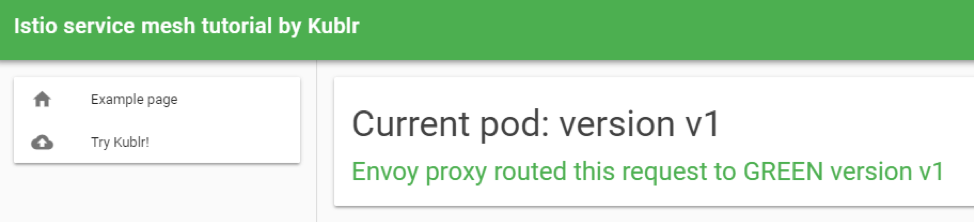
The exact configuration which makes our “website” Kubernetes service point only to single deployment is the Istio VirtualService we created for the website. It tells the Envoy proxy to route requests of “website” service only to pods with label “version: website-version-1” (you probably noticed that the manifest of service “website” selects only one label “app: website” from our pods but says nothing about the “version” label to pick from – so without Envoy logic the Kubernetes service itself would do round robin between all pods with “app: website” label, both version one, two and three). You can change the version of the website that we see by changing the following section of the VirtualService manifest and redeploying it:
  http:
  - route:
    - destination:
        host: website
        subset: version-1
The “subset” is where we chose the correct section of DestinationRule to route to, and we will learn in depth about these resources in the next tutorial.
Usually when new version of an application needs to be tested with a small amount of traffic (canary deployment), the vanilla Kubernetes approach would be to create a second deployment that uses a new Docker image but the same pod label, causing the “service” that sends traffic to this pod label, while also balancing between the newly plugged pods from the second deployment. It is not as flexible as an Istio solution. You cannot easily point 10% of traffic to the new deployment (in order to reach a precise 10% you will need to keep the pod replicas ratio between two deployments according to the needed percentage, like 9 “v1 pods” and 1 “v2 pod”, or 18 “v1 pods” and 2 “v2 pods”), and cannot use HTTP header for example to route requests to particular version.
Istio solves this limitation through its flexible VirtualService configuration. For instance, if you want to route traffic using the 90/10 rule, it can easily do it like this:
apiVersion: networking.istio.io/v1alpha3
kind: VirtualService
metadata:
  name: website-virtual-service
spec:
  hosts:
  - "*"
  gateways:
  - website-gateway
  http:
  - route:
    - destination:
        host: website
        subset: version-1
      weight: 90
    - destination:
        host: website
        subset: version-2
      weight: 10
The source code for the article is available on github: https://github.com/kublr/istio-blog-sample.
We hope this tutorial provided you with a good high-level overview of Istio, how it works, and how to leverage it for more sophisticated network routing. Istio streamlines implementation of scenarios that would otherwise require a lot more time and resources. It is a powerful technology anyone looking into service meshes should consider. In our next post, Hands-on Canary Deployments with Istio, we will use a custom HTTP header value to let Istio route our requests to correct versions of the web service. By doing that we will have full control of the traffic flow and will analyze the tracing results in Zipkin dashboard.